
How To Install A Dimmer Switch?
Two wires in a switch box often means both are hot — the standard switch-loop wiring in homes built before 2011. Knowing which is line and which is load before you touch anything is what keeps the install safe.
 Eugen
EugenEugen Nikolajev
Creator of LED Lighting Info
Hi, I am Eugen. I was always one of those kids who had all sorts of weird lighting gadgets for every occasion.
Now, I want to share my knowledge and experience about lighting with you on LED Lighting Info.
Read my editorial standards
Key Takeaways
Connect the line (incoming hot) to the dimmer's line lead, the dimmer's load lead to the wire feeding the fixture, and the ground if present. For 3-way circuits, the two travelers run between the dimmer and the companion switch.
Many newer dimmers also have a neutral lead, required at most switch boxes by NEC 404.2(C) since 2011.
Most light switches connect with two wires — the hot comes in, and a wire carries on to the rest of the circuit, completing the loop. Dimmers are similar, but with a few important differences worth knowing before you start.
Here's what this guide covers:
- Wires used by single-pole and 3-way dimmers
- How to install both types step by step
- Leading-edge vs. trailing-edge dimmers and LED compatibility
- Common troubleshooting fixes
- Whether you can use a dimmer with recessed lights
⚠️ Safety first: turn off the breaker for the circuit you're working on, then verify the wires are dead with a non-contact voltage tester before you touch anything. Don't trust the wall switch to isolate power, switch loops and multi-wire circuits can leave conductors energized even when the switch is off.
How Many Wires Do Dimmer Switches Have To Connect?
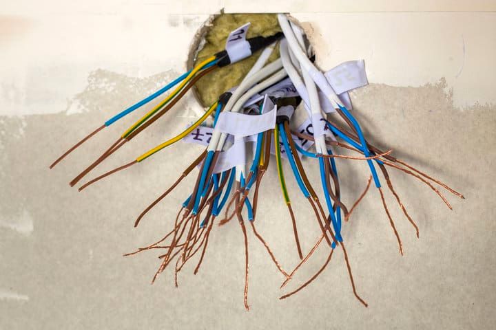
Quick definitions: the line (or line wire) is the always-hot conductor coming from the breaker panel. The load (or load wire) is the conductor that runs from the switch to the fixture and only carries current when the switch is on.
There are two basic dimmer types — a single-pole dimmer that controls a fixture from one location, or a 3-way dimmer wired alongside a second switch so you can control the same fixture from two spots. The UK and EU equivalent is called a 2-way dimmer (same function, different naming convention). When a third switching location is needed, the U.S. calls that a 4-way switch and the UK calls it an intermediate switch.
Here's how the two dimmer types compare at a glance:
| Feature | Single-Pole | 3-Way |
|---|---|---|
| Number of switches in the circuit | 1 | 2 |
| Leads on the dimmer (excl. neutral) | 3 (line, load, ground) | 4 (common, 2 travelers, ground) |
| Common terminal | No | Yes |
| Traveler wires | No | 2 |
| Dims from both locations | N/A | Only with companion dimmer set |
A modern single-pole dimmer typically has a line lead (connects to the incoming hot from the panel) and a load lead (connects to the wire feeding the fixture), plus a green or bare ground. Both leads are usually colored black, or one black and one red, but their function is what matters — only the line is energized when the dimmer is off. Many electronic and smart dimmers also have a neutral lead (white), which must connect to the circuit neutral.
On a 3-way dimmer, the dimmer side has a common terminal plus two traveler terminals, plus a ground. The common connects either to the incoming line or the wire feeding the fixture, depending on which end of the run the dimmer sits at, and the two travelers run between the dimmer and the companion switch.
Note: in a 3-way circuit, only one of the two switches can be a dimmer — the other is a standard 3-way (on/off) switch. If you bought a 3-way dimmer but only need it on a single-pole circuit, cap the unused traveler lead with a wire nut.
For both types, the ground lead is bare copper, green, or green with a yellow stripe. If the box has a ground wire in the circuit, connect them. If the box doesn't, see the GFCI guidance under the single-pole installation below — don't just cap the dimmer's ground lead.
How To Install A Dimmer Switch
Power off at the breaker first, and verify the wires are dead with a non-contact voltage tester before you touch anything.
Installing A Single-Pole Dimmer
Turn off the breaker and confirm both wires in the box are dead with a non-contact voltage tester.
- Connect the dimmer's line lead to the incoming hot in the box (typically black).
- Connect the dimmer's load lead to the wire that runs from the box to the fixture.
- If the dimmer has a neutral lead (white), connect it to the circuit neutral. Most electronic and smart dimmers require this.
- Connect the dimmer's ground (green or bare) to the equipment ground in the box. If there is no equipment ground, see the next subsection.
- Tuck the wires into the box, screw the dimmer to the strap, and attach the wall plate.
- Restore power at the breaker and test.
No Ground In The Box
NEC 250.130(C) and 406.4(D)(2) allow a code-compliant retrofit on ungrounded circuits if you add GFCI protection — either by installing a GFCI breaker at the panel or a GFCI receptacle/device upstream of the dimmer — and label the device "No Equipment Ground." The receptacle-level GFCI is usually the simpler retrofit. GFCI protects against shock from line-to-ground faults but does not replace a true equipment grounding path. If you can run a proper grounding conductor instead, do that. Capping the dimmer's ground lead without one of these remedies leaves the metal yoke unbonded and is not compliant.
Note: NEC 210.8 only requires GFCI protection in specific locations (bathrooms, kitchens, laundry rooms, garages, unfinished basements, outdoors, near pools, and certain hardwired appliances) — not on every general-lighting circuit. Older homes can still have ungrounded circuits in living areas, in which case a GFCI device is the standard retrofit. Reference: the National Electrical Code.
Installing A 3-Way Dimmer
In a 3-way circuit, the dimmer goes on one switch location and a standard 3-way switch goes on the other. Label every wire with masking tape before you disconnect anything — it saves a lot of grief.
- Turn off the breaker and verify all wires in both boxes are dead.
- Identify the common terminal on each switch. It's labeled, and on the dimmer, the common lead is usually a different color from the travelers.
- Connect the incoming hot from the panel to the common terminal at the first switch (the line end of the run).
- Connect the wire feeding the fixture to the common terminal at the second switch (the load end of the run).
- Connect the two travelers between the switches: one traveler on switch 1 to one traveler on switch 2, and the remaining traveler on switch 1 to the remaining traveler on switch 2. Either pairing works as long as both ends connect.
- Connect the ground leads on both switches to the circuit ground.
- If the dimmer has a neutral lead, connect it to the circuit neutral.
- Restore power and test from both locations.
Only one switch in the pair dims; the companion acts as a plain on/off. To dim from both locations, you need a companion dimmer set — matched units sold by the same manufacturer. They won't mix between brands.
If you're running a 3-way circuit where there wasn't one before, you'll need to pull cable to the second switch location, which usually means cutting drywall and patching afterward. Make sure ground wires are connected throughout, or follow the GFCI guidance above if there's no equipment ground.
How To Wire A Dimmer With Only 2 Wires In The Box
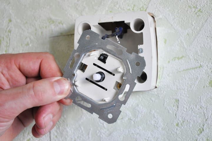
Two wires in a switch box almost always mean a switch loop — a wiring style common in U.S. homes built before the 2011 NEC. In a switch loop, both conductors are hot: one is the incoming line, and the other is the switched hot (the load) that returns to the fixture. There's no neutral in the box, and likely no separate equipment ground unless the cable includes one.
Per NEC 200.7, when a white conductor is used as a switched hot in a switch loop, it should be re-identified with black tape at every visible end. If you don't see that marking, test with a non-contact voltage tester to figure out which is line and which is load — the line stays hot whenever the breaker is on; the load is only hot when the upstream switch is on.
- Turn off the breaker and confirm both wires are dead.
- Identify which conductor is the line and which is the load using a voltage tester (briefly restore power for the test, then turn it off again before connecting).
- Connect the line conductor to the dimmer's line lead.
- Connect the load conductor (the one returning to the fixture) to the dimmer's load lead.
- If your dimmer requires a neutral and there isn't one in the box, switch to a no-neutral-required dimmer or run new cable that includes a neutral.
- Handle the ground per the "No Ground In The Box" guidance above — don't simply cap the dimmer's ground lead.
If you bought a 3-way dimmer but only have a switch loop, cap the unused traveler lead with a wire nut and treat the rest as a single-pole install.
If you need to run a new conductor as a switched hot, use black or another non-reserved color. Avoid red — red is conventionally a traveler in 3-way circuits or the second hot in 240V branches, and using it for a single-pole switch loop will confuse anyone troubleshooting later. Never use white or gray (reserved for neutral) or green/bare (reserved for ground) for a hot conductor.
LED Compatibility: Leading-Edge vs. Trailing-Edge Dimmers
Most modern dimmers fall into one of two categories:
- Leading-edge (TRIAC) dimmers — the older standard, designed for resistive loads like incandescent and halogen bulbs. They chop the front of each AC half-cycle. Many work with LEDs but often produce flicker, buzz, and a narrow dimming range.
- Trailing-edge (electronic / ELV) dimmers — designed for electronic loads, including most LED drivers and low-voltage transformers. They generally produce smoother, quieter dimming with LEDs.
Match the dimmer to the load. For LEDs, get a dimmer rated for LED loads (typically labeled "LED/CFL" or trailing-edge), and check the manufacturer's compatibility list — Lutron, Leviton, and others publish tested combinations. Pairing an old incandescent-only dimmer with LED bulbs is one of the most common causes of flicker and limited dimming range, even when the bulb is dimmable.
Minimum Load Requirements
Many dimmers — especially LED-rated ones — have a minimum load. If the bulb's wattage is below that minimum (a single 7W LED on a dimmer rated 25W–600W, for example), the dimmer can drop out, flicker, or behave erratically. Check the dimmer's spec sheet, and if the load is too small, either add more fixtures on the circuit or pick a dimmer rated for low-load operation.
Smart and Wi-Fi Dimmers
Smart dimmers — Wi-Fi, Zigbee, Z-Wave, Matter — almost always need a neutral wire in the box because the radio and electronics draw a small standby current. NEC 404.2(C) has required a neutral at most switch boxes since 2011, but older switch loops typically don't have one. A handful of brands sell "no-neutral" smart dimmers for retrofits; they have stricter minimum-load requirements and may not work with all bulbs. Either way, check the wiring requirements before you buy.
Troubleshooting: Common Problems With Dimmer Switch Wiring
The Light Is On When Both Switches Are Off (3-Way Circuit)

This is a wiring mismatch on the second switch — the common and a traveler are swapped, so the circuit can complete with both switches in the "off" position.
- Turn off the breaker.
- At the second switch, swap the wires on the two traveler terminals.
- Restore power and test from both locations.
The Dimmer Switch Is Upside Down
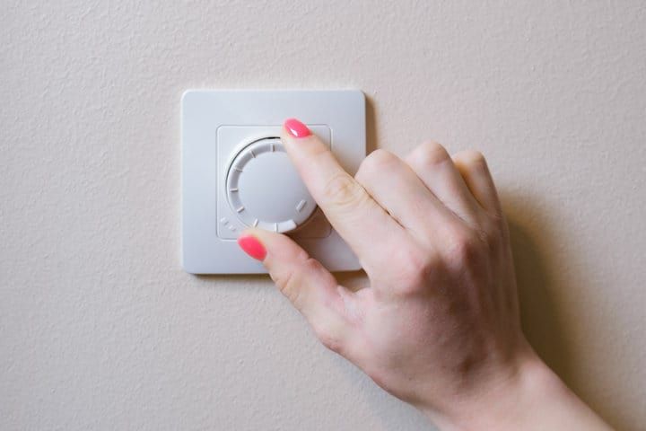
If the entire dimmer is physically upside down, just remove it, rotate, and reinstall it.
If it's a 3-way dimmer where the on/off direction is reversed but the dimmer is upside down in behavior only, you've wired one of the travelers into the common terminal.
- Turn off the breaker.
- Check the dimmer's manual or the markings on the device to identify the common and traveler terminals.
- Rewire so the line (or fixture wire) lands on common and the two travelers connect to the traveler terminals.
- Restore power and test.
The Lights Won't Dim

Work through these in order — the most common causes first:
- Confirm the bulbs are explicitly marked dimmable. Most LED bulbs are not dimmable by default; the package will say so.
- Confirm the dimmer matches the load type — leading-edge for incandescent/halogen, trailing-edge or LED-rated for LEDs. A mismatch is a very common cause of "won't dim" or "barely dims."
- Check the dimmer's wattage rating. If the total load on the circuit exceeds the rating, the dimmer falls back to acting as an on/off switch.
- Check the dimmer's minimum-load spec. Too little load can also break dimming.
- If the above all check out, swap in a known-good dimmer. If the new one works, the original is faulty.
The Lights Only Work From One Switch (3-Way Circuit)
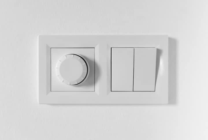
The light works, so neither switch is broken — but the circuit is wired so that one switch effectively bypasses the other.
- Turn off the breaker.
- Pull both switches and label every wire as you disconnect them.
- Verify that travelers run between the two switches, and that line and load each land on a common terminal (line at one end of the run, load at the other).
- Reconnect with the correct mapping, restore power, and test from both locations.
The Dimmer Makes A Loud Buzzing Sound
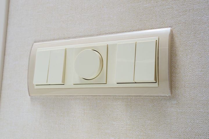
Some buzz from older dimmers is normal, but a loud hum from a modern dimmer usually points at one of three things:
- Turn off the breaker and check for loose wire connections — a loose wire can arc, buzz, and eventually trip the breaker. Tighten everything.
- Check whether the dimmer is overloaded (total wattage above the dimmer's rating). Reduce the load or upsize the dimmer.
- Confirm the dimmer matches the load type. A leading-edge dimmer driving LED loads is a common source of buzz; switch to a trailing-edge / LED-rated dimmer.
- If none of the above, replace the dimmer.
Can You Put A Dimmer Switch On Recessed Lights?
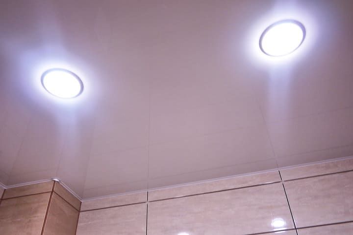
Recessed lights work fine with a dimmer, provided you use dimmable bulbs or a dimmable fixture. Two things to check:
- Replaceable-bulb fixtures: confirm the bulbs are marked dimmable, and match the dimmer to the load type (LED-rated for LEDs).
- Sealed integrated-LED fixtures: the entire fixture must be dimmable. Check the spec sheet, and prefer fixtures that publish a compatibility list of tested dimmers.
Older sealed halogen recessed lights are essentially always dimmable. Sealed LED fixtures need more care because flicker and limited dimming range are very common when the dimmer and driver aren't a tested pair.
Final Words
Wiring a dimmer comes down to a few principles: kill power at the breaker and verify with a tester before touching wires, get the line/load distinction right, match the dimmer to the load type (especially with LEDs), and handle the ground properly when the box doesn't have one. Label your wires before you disconnect anything, and you'll save yourself most of the troubleshooting in this guide.